MID. HH Marquee Letter PCB
- Astro Lee

- Sep 9, 2024
- 4 min read
What a dynamic journey this was. I'm writing this blog after I finished the Marquee letter. It was hell of a ride!
To start from the very beginning, I was assigned the letter R for my Marquee letter.
from the phrase "Start Crying" for the whole class.
My R was the crying 'r'.
(My first attempt in milling the board) - I was happy with how clean and pretty it is


I was using the big Bantam to mill the board.

(close up of milling - it was loud but fun)

And close ups after soldering the board!
(Including the gunky fixes I made with the soldering iron)


(And the close up of the past potentially-troublesome power & parts area)
--> At this time, I was very hopeful in what I made. I was prepared and cautious with every step.
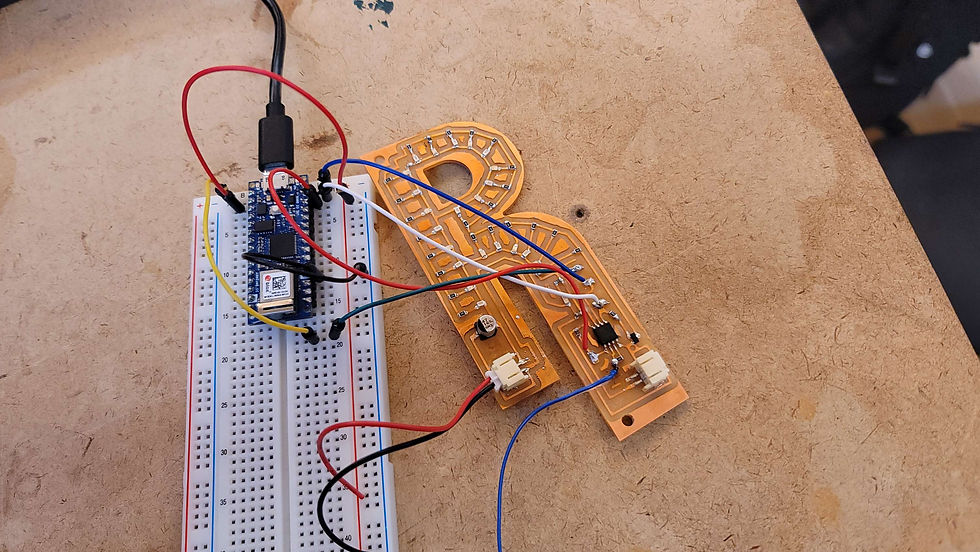
The full size picture of the first board.

I was confident with the wires and the design, not knowing how many times I would fail after this.
And the first attempt of uploading the code began.

I was very hopeful at first because the board lit up perfectly the moment I plugged the power in.


(Very happy fingers proudly showcasing the board)
Then I attempted to program the AtTiny on the board, which I failed with every attempt I made.

Whenever I attempted to burn the bootloader on the AtTiny, it always returned this error, and I never went past this stage.
So I tried to come back to this issue later on. I tried various debugging methods, with different computers, different AtTiny, different Arduino as ISP. It was odd because the board was lighting up the power LED, and also responding to the code --> LEDs picking up the code signals in the video

But it never worked.
So I started trying every debugging method I can think of. Below is a picture of me attempting to program another AtTiny again after trying to separate the rest of the board (LEDs) from the AtTiny Area (I got an advice from a second year ITP student saying I should try separating the power line from the coding area and the rest of the board, because of some electrical phenomenon)- you can see the solder gunk on the right edge of the board.

Then that didn't work either. So I was on the floor until 2 in the morning to go past this stage (burning the bootloader), but I never went past that stage.

This process was extra frustrating, because my board would act somewhat normal before I attempted to burn bootloader, reacting to power and physical interaction, but not in the correct way --> and then once I attempted to burn bootloader, it just turned half dead and only lighted the power LED -which was also a correct behavior of sort-. Below are some strangely behaving PCB moments with the first PCB I made -before I attempted to code it. (Yes, there is a second version that comes later)
And as a final attempt, I tried adding LEDs for debugging, following the Capacitive Sensor Documentation (more so the notes in the Arduino Sketch)
-The Red meant a warning
-The yellow heartbeat was a recognition signal of the AtTiny
-The green LED was a success signal for the Arduino-AtTiny connection establishment. I never got to see this one.
So, I slowly and although very late, realized that there is no breakthrough with this board. I tried swapping out everything. The AtTiny, the resistor, beep tested everything -including the wires, the Arduino, the Programming Computer, ... but nothing got me past the bootloader stage.
And after the Homemade Hardware class, and I talked with Andy (was still confused as it seemed like there was no clear reason why this didn't work) My best guess was that the weak and sloppy wire connection -the ground and power when I was attempting to code the PCB, corrupted the code somehow and fried my AtTiny. And at this point, I soldered and desoldered too much parts, and the power and capacitive sensor copper was falling off, and my first PCB was in a really bad, sloppy condition.
So I decided to restart.
And in the middle of this process, when I was working on my first board, attempting to fix the bug I had, I had an office hour with Bianca, ITP's Pcomp-goddess resident, and she helped me fix the issue I had with the AtTiny Project - Capacitive Sensor LED lighting project on the breadboard -which helped me understand the process and the micro controller better. Below are some still shots and videos of the accomplishments she helped me achieve. (She really fixed it, haha I observed on the side)
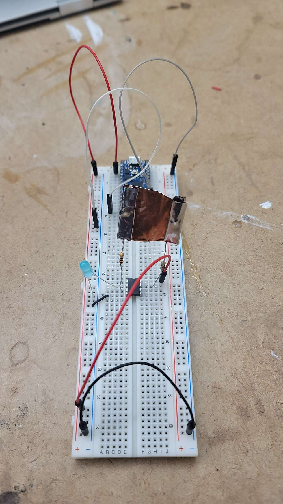
Essentially the issue I had with this project was that I was confused with AtTiny's Analogue, Digital, and Programming pin numbers -so I got the numbers wrong when I was programming it-, and when soldering the resistor+copper sheet, it was done badly, as the solders weren't fully in contact with the metal, which caused it to be a bad sensor (in the process of making a custom capacitive sensor). Bianca solved this problem by using the copper tape ITP had. This created a much more stable sensor, and allowed it to really react well to the touch.
And now with all these failed attempts, I learned a lot, and I came back another morning, in solitude to really sit through this issue I was having. I started back from inspecting my PCB design in Fusion.

I cleaned up the wire area around the AtTiny, to make it less-shorty and more organized.
Then I moved on to milling again.
... To be updated


Comments